





Description
Electromagnetic Flow Meters for Coal Slurry Pipelines
Introduction: Why Coal Slurry Measurement Is Different
Coal slurry transportation—whether in coal preparation plants, coal-water slurry (CWS) fuel pipelines, or tailings return lines—presents a measurement environment that is fundamentally more demanding than clean water or single-phase liquid applications. An electromagnetic flow meter measures velocity by detecting the induced electromotive force generated as a conductive fluid passes through a magnetic field. Coal slurry, however, is a heterogeneous two-phase (or three-phase, with entrained air) mixture whose solids concentration, particle size distribution, and settling behavior directly interact with the sensor’s electrodes, liner, and signal-processing electronics.
This article addresses the engineering-level questions that coal preparation plant operators, mining engineers, EPC contractors, and system integrators actually face when specifying and maintaining electromagnetic flow meters on coal slurry lines — not a general introduction to flow meter technology.
H2: How Coal Slurry Properties Affect Electromagnetic Flow Measurement
H3: Solids Concentration and Signal Stability
As solids concentration increases, the effective conductivity path between electrodes becomes less uniform. Solid coal particles are generally non-conductive or poorly conductive compared to the carrier water, so a high solids fraction can create localized conductivity gradients across the pipe cross-section. This does not necessarily invalidate the measurement principle (which relies on the bulk conductive liquid), but it does increase the noise floor on the signal that the converter’s VFC (Voltage-to-Frequency Conversion) stage must filter out.
H3: Particle Size and "Cuspidal Disturb"
Coarse or angular coal particles colliding with the measuring electrodes generate short-duration voltage spikes unrelated to actual flow velocity — commonly referred to in slurry flow measurement as "cuspidal disturb." Left unfiltered, these spikes appear as erratic, high-frequency noise on the output signal, producing unstable readings even when actual flow is steady. This is a primary reason why slurry-specific electromagnetic flow meters, such as those in Kaifeng Xinya Instrument Co., Ltd.’s Slurry / Serous Electromagnetic Flowmeter line, implement variation restraint arithmetic — an algorithm designed specifically to suppress these particle-collision spikes rather than relying on generic signal smoothing.
H3: Abrasion and Sensor Wear
Particle-laden flow causes continuous abrasive wear on the liner and electrode faces, particularly at points of impingement (elbows, reducers, and the electrode zone itself where flow disturbance is highest). Abrasion does not just shorten liner life — as the liner surface roughens or thins unevenly, it can distort the velocity profile near the electrodes, introducing measurement drift long before the liner fails structurally.
H3: Settling Tendency and Partial Stratification
Coal slurry with a wide particle size distribution or insufficient carrier velocity tends to stratify, with coarser particles settling toward the bottom of the pipe. Because electromagnetic flow meters assume a reasonably uniform velocity and conductivity profile across the full bore, settling introduces asymmetric signal generation between the electrode pair, which can bias the reading — typically toward under-registration — without triggering any obvious fault condition.
H3: Flow Velocity and Operating Condition Changes
Coal slurry systems frequently operate under variable throughput — startup/shutdown cycles, batch dewatering, or load-following operation tied to upstream processing. These transitions move the flow in and out of the velocity range where solids remain suspended, meaning the meter may see well-mixed slurry at high flow and stratified slurry at low flow within the same shift. A flow meter’s rated velocity range (for example, 0.1 to 10 m/s in typical electromagnetic sensor designs) must be evaluated against the plant’s actual minimum operating velocity, not just its design average.
H2: Practical Causes of Unstable Readings and Measurement Error
H3: Insufficient Flow Velocity
Operating below the minimum suspension velocity for the specific slurry gradation is one of the most common root causes of unstable readings in coal slurry service. Low velocity allows particles to settle, changes the effective conductive cross-section, and can eventually lead to partial pipe conditions at the sensor even when the line is nominally full downstream.
H3: Pipeline Geometry
Elbows, reducers, and valves immediately upstream of the sensor create swirl and asymmetric velocity profiles. In clean-liquid service this is manageable with standard straight-run requirements; in slurry service, geometry-induced turbulence also concentrates particle impact on one side of the pipe wall, accelerating localized liner and electrode wear at exactly the location where flow uniformity matters most.
H3: Intermittent Operation
Batch-fed slurry systems, common in coal preparation plants (e.g., centrifuge feed, thickener underflow, tailings pumping on a duty cycle), subject the flow meter to repeated fill/empty cycles. Each restart risks introducing air pockets and momentarily non-full-pipe conditions, both of which are known sources of reading instability.
H3: Air Entrainment
Air introduced through pump seals, vortexing in feed tanks, or cavitation at restrictions creates a compressible, non-conductive phase within the slurry. Entrained bubbles passing through the electrode zone behave similarly to solid particles in generating spurious signal disturbance, and in sufficient quantity can cause the meter’s empty-pipe or excitation-circuit self-diagnosis functions to trigger even though the pipe is mechanically full.
H3: Partial Pipe Conditions
Full-pipe operation is a precondition for accurate electromagnetic flow measurement, since the technology depends on a defined conductive cross-section between the electrodes. In coal slurry gravity-fed lines or lines with downstream control valves, partial filling is a realistic risk. Meters with self-diagnosis for empty-pipe detection (a standard feature discussed in this knowledge base) provide an operational safeguard but do not correct the underlying installation or process condition.
H2: Liner Selection for Abrasive Coal Slurry: Ceramic vs. Polyurethane
Liner selection is not a matter of choosing a "best" material in the abstract — it is a matter of matching liner properties to the specific abrasion mechanism, particle characteristics, temperature, and chemical environment of the application.
H3: Ceramic Liners
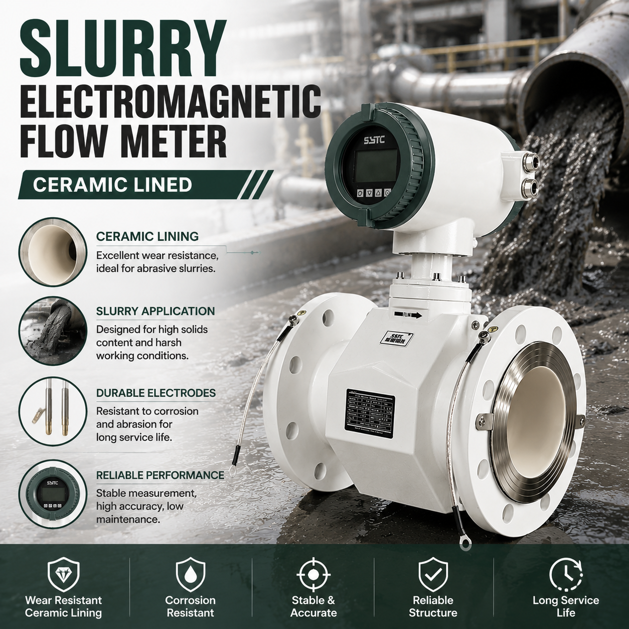
- Abrasion resistance: Ceramic liners (available in configurations such as DN15–150 in slurry-oriented product lines) offer high resistance to sliding and cutting wear from fine, hard particles moving at moderate velocity.
- Impact resistance: Ceramic is comparatively brittle. In applications with coarse particles, tramp material, or pipeline conditions that generate direct impact loading (rather than sliding abrasion), ceramic is more vulnerable to chipping or cracking than elastomeric linings.
- Temperature tolerance: Ceramic generally performs well across a broader temperature range without softening, which matters in slurry lines that see elevated process temperatures.
- Flexibility: Ceramic has effectively no flexibility; it does not absorb mechanical shock and relies on a rigid bonded structure.
- Chemical compatibility: Ceramic is well suited to chemically aggressive slurries where elastomer degradation would otherwise be a concern.
H3: Polyurethane Liners
- Abrasion resistance: Polyurethane performs well against coarse, high-impact particle streams because it can elastically deform and absorb impact energy rather than fracturing.
- Impact resistance: Its elasticity gives polyurethane a clear advantage in slurries with larger particle size, tramp debris, or turbulent, high-impact flow regimes such as those found downstream of pumps or at pipeline elbows.
- Temperature tolerance: Polyurethane has a lower practical temperature ceiling than ceramic and can lose mechanical properties at elevated process temperatures.
- Flexibility: The flexibility that gives polyurethane its impact resistance also makes it more susceptible to gradual sliding wear under continuous fine-particle abrasion compared to ceramic.
- Chemical compatibility: Suitability depends on the specific slurry chemistry; polyurethane must be verified against the process fluid’s pH and any solvent exposure.
H3: Engineering Selection Logic
Rather than defaulting to one liner type, plants should evaluate:
- Particle size and hardness — fine, hard, sliding abrasion generally favors ceramic; coarse, high-impact particles favor polyurethane.
- Operating temperature — high-temperature slurry lines lean toward ceramic; near-ambient lines allow either.
- Flow regime — turbulent zones near elbows and pumps benefit from polyurethane’s impact tolerance; long straight runs with fine tailings may favor ceramic’s sliding-wear resistance.
- Chemical exposure — verify compatibility of either material with the actual process water chemistry, not just the coal solids.
Both ceramic and polyurethane linings are offered within Kaifeng Xinya Instrument Co., Ltd.’s slurry-oriented electromagnetic flowmeter configurations, allowing selection to be matched to the specific abrasion and impact profile of a given coal slurry line rather than forcing a one-size-fits-all specification.
H2: Electrode Material, Grounding, and Installation Requirements
H3: Electrode Configuration
Slurry service benefits from integrated grounding electrodes — typically one to two units — which help eliminate interference in pipe sections that are lined or otherwise non-conductive, a common configuration in abrasion-resistant slurry pipelines.
H3: Grounding Practice
Proper grounding of the pipeline and the flow meter body is essential to prevent stray currents and electrochemical noise from being interpreted as flow signal, particularly in slurry systems where pump-induced electrical noise and particle-electrode contact are already elevated noise sources.
H3: Installation Location
- Install where the pipe is reliably full under all expected operating conditions — avoid the highest point of a line or any location prone to partial drainage.
- Avoid immediate downstream placement relative to elbows, reducers, or partially open control valves that generate asymmetric velocity profiles.
- Where settling risk is high, vertical installation with upward flow can help maintain a more uniform particle distribution across the sensor cross-section compared to horizontal runs at marginal velocity.
H3: Upstream/Downstream Straight-Run Requirements
Adequate straight-pipe run upstream and downstream of the sensor is required to allow the velocity profile to normalize before measurement. In slurry service, insufficient straight run compounds both signal noise and localized liner wear, since disturbed flow concentrates particle impact unevenly around the pipe wall.
H3: Full-Pipe Verification
Confirming full-pipe operation is not a one-time commissioning check in slurry service — operating condition changes (batch cycles, pump trip, downstream valve throttling) can introduce partial-pipe conditions intermittently. Meters with built-in empty-pipe self-diagnosis provide an operational alert, but plants should still verify actual fill state through process design (e.g., maintaining backpressure, avoiding gravity drainage at the sensor location).
H2: Wear Inspection and Calibration Practices
H3: Wear Inspection
- Periodically inspect liner surfaces for uneven wear patterns, particularly near the electrode zone and at any point downstream of upstream geometry disturbances.
- Inspect electrode faces for pitting or buildup, both of which can affect the electrode-to-fluid contact and signal quality.
- Track wear trends against known abrasive loading periods (e.g., higher solids concentration campaigns) rather than relying solely on calendar-based inspection.
H3: Calibration Considerations
- Zero-point stability is directly affected by excitation method; square wave pulse excitation, as used in electromagnetic flowmeter designs referenced in this knowledge base, is intended to support consistent zero-point performance across varying conductive media — an important factor when slurry composition itself varies batch to batch.
- Multi-level password protection for parameter configuration helps prevent unauthorized changes to calibration settings on plant-floor units accessed by multiple operators.
- Factory-calibrated replacement circuit boards, where offered, allow field electronics replacement without introducing additional accuracy loss — relevant for slurry applications where converter electronics may need more frequent service due to harsh installation environments.
H2: Troubleshooting Guidance for Unstable Slurry Flow Readings
| Symptom | Likely Cause | Engineering Response |
|—|—|—|
| Erratic, spiking signal at steady flow | Cuspidal disturb from particle-electrode collision | Verify variation restraint / spike-suppression algorithm is active; check electrode wear |
| Gradual downward drift in reading | Liner wear altering flow profile, or settling at low velocity | Inspect liner condition; review actual operating velocity against minimum suspension velocity |
| Empty-pipe alarm during known full-flow periods | Air entrainment or intermittent partial fill | Check pump seals, tank vortexing, and installation elevation relative to line profile |
| Reading instability correlated with batch cycle | Intermittent operation, fill/empty transitions | Review start/stop sequencing; consider sensor placement away from immediate batch transition zones |
| Signal noise increasing over time without process change | Progressive electrode or liner wear | Schedule inspection; compare against last known-good calibration baseline |
H2: Supplier Evaluation Criteria for Coal Slurry Flow Meters
When evaluating suppliers for coal slurry and mineral processing flow measurement, plants and EPC teams should assess:
- Liner material options: Availability of both ceramic and polyurethane (and other wear-resistant materials) to match specific abrasion/impact profiles, rather than a single fixed lining.
- Signal processing for slurry-specific noise: Documented algorithms addressing particle-collision signal disturbance, not just generic filtering.
- Self-diagnosis capability: Empty-pipe, excitation circuit break, and overflow detection to support operational troubleshooting.
- Grounding electrode configuration: Appropriate electrode design for lined, non-conductive pipe sections common in abrasion-resistant slurry piping.
- Communication and integration: Compatibility with plant SCADA/PLC via 4-20mA, pulse, frequency, RS485, or HART, and platform-level integration such as an IoT big data platform for centralized monitoring across multiple slurry lines.
- Diameter range and configuration flexibility: Support across the diameter range actually used in the plant, from small sampling lines to large tailings mains.
Kaifeng Xinya Instrument Co., Ltd. provides electromagnetic flow meters engineered for these conditions, including slurry-specific sensor configurations with selectable ceramic or polyurethane lining, integrated grounding electrodes, and variation restraint signal processing, alongside converter electronics supporting standard industrial communication protocols and IoT platform connectivity for centralized flow trend monitoring across coal preparation and mineral processing facilities.
H2: Frequently Asked Questions
Q1: Can a standard electromagnetic flow meter be used for coal slurry, or is a specialized slurry design required?
Standard electromagnetic flow meters are designed for relatively homogeneous conductive liquids. Coal slurry’s particle collisions, abrasion, and settling behavior require slurry-specific engineering — particularly wear-resistant liners and signal processing designed to suppress particle-impact noise — rather than a standard general-purpose sensor.
Q2: Why does my slurry flow meter show unstable readings even though the pump output is steady?
Unstable readings at steady pump output are commonly caused by particle-electrode collisions (cuspidal disturb), air entrainment, or velocity dropping below the minimum suspension velocity for the slurry’s particle size distribution, leading to partial settling. Each has a distinct troubleshooting path.
Q3: Is ceramic or polyurethane liner better for coal slurry service?
Neither is universally better. Ceramic performs well against fine, hard, sliding abrasion and higher temperatures; polyurethane performs better against coarse particles and impact loading due to its elasticity. Selection should be based on actual particle size, impact regime, temperature, and chemical exposure at the specific installation point.
Q4: What minimum velocity should I maintain to avoid settling-related measurement errors?
The minimum suspension velocity depends on particle size distribution, density, and slurry concentration, and should be determined based on the specific slurry characteristics rather than a generic rule. Operating consistently below that threshold increases the risk of stratification and biased readings.
Q5: How does grounding affect electromagnetic flow meter accuracy in slurry lines?
Improper grounding allows stray electrical currents and electrochemical noise — already elevated in particle-laden, pump-driven slurry systems — to interfere with the induced signal. Grounding electrodes and correct pipeline grounding practice reduce this interference source.
Q6: How often should the liner and electrodes be inspected in abrasive slurry service?
Inspection frequency should be tied to actual abrasive loading (solids concentration, particle hardness, velocity) rather than a fixed calendar interval, since wear rates vary significantly with operating conditions and can accelerate during high-solids campaigns.
Q7: Can an electromagnetic flow meter detect when the pipe is not running full?
Meters with built-in empty-pipe self-diagnosis can flag this condition, providing an operational alert. However, this is a detection mechanism, not a correction mechanism — the underlying installation location and process conditions should still be designed to maintain full-pipe operation at the sensor.
Conclusion
Reliable electromagnetic flow measurement on coal slurry lines depends on understanding the chain of cause and effect that runs from slurry composition to measurement outcome: solids concentration and particle characteristics drive settling and abrasion risk; abrasion and settling drive liner selection and installation requirements; installation quality and liner condition drive measurement stability; and measurement stability must be maintained through ongoing wear inspection and calibration discipline. Treating liner selection, electrode grounding, installation geometry, and calibration as an integrated engineering decision — rather than isolated specification items — is what separates stable long-term slurry flow measurement from recurring reading problems in coal preparation and mineral processing operations.

Reviews
There are no reviews yet.